春节快乐!
我们将在 2 月 1 日至 8 日期间休假,并将于2 月 9 日恢复办公。
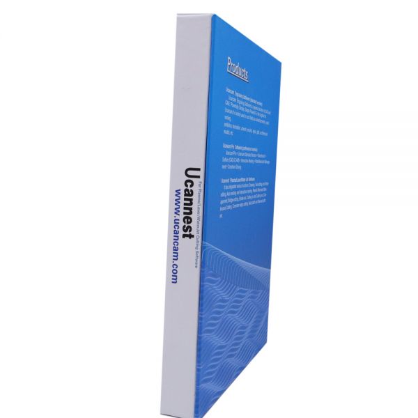
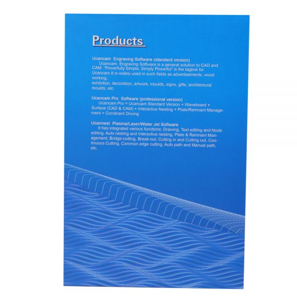
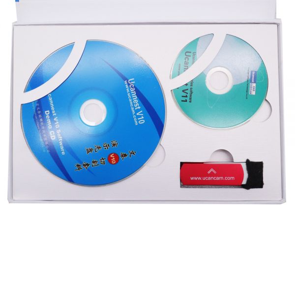
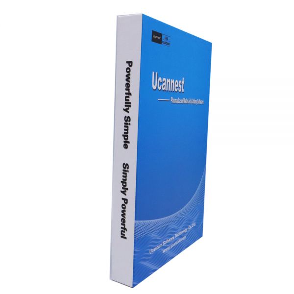
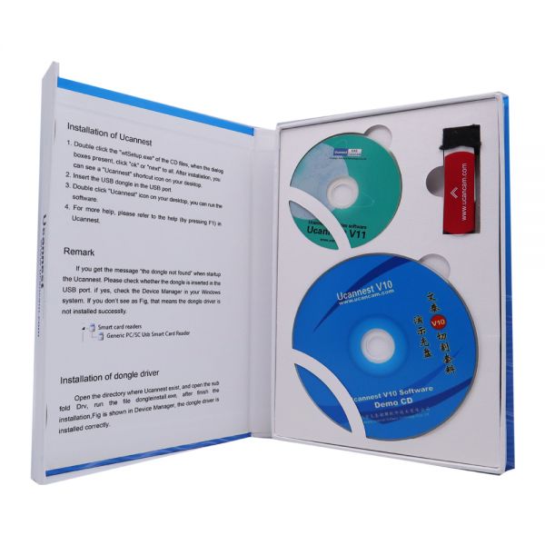
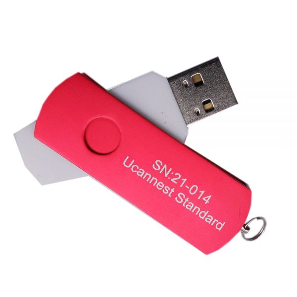
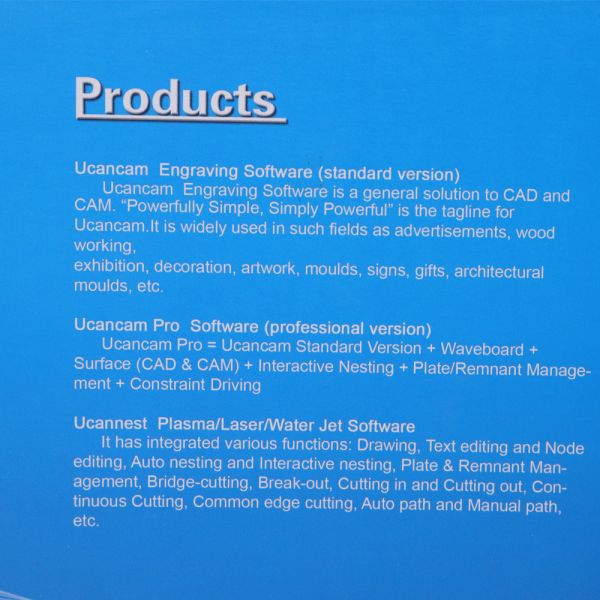
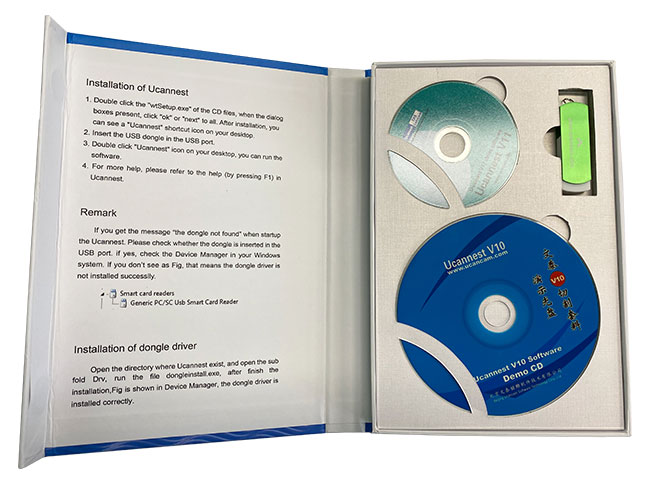
Ucannest V11 Standard Version CNC Engraving Software for CNC Plasma Cutting Machine
单件价格
MXN 6,450.00
/pc
批量折扣
数量
折扣
单价
1
0%
MXN 6,450.00
总费用
MXN 6,450.00
数量
/pc
1
春节快乐!
我们将在 2 月 1 日至 8 日期间休假,并将于2 月 9 日恢复办公。
Ucannest V11 Standard Version CNC Engraving Software for CNC Plasma Cutting Machine
单件价格
MXN 6,450.00
/pc
批量折扣
数量
折扣
单价
1
0%
MXN 6,450.00
总费用
MXN 6,450.00
数量
/pc
1
 |
|
 |
|
 |
|
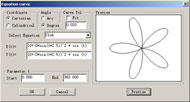 |
Equation Curve The software can automatically generate the curve described in the equation like this: X=fx(t) R=r(t) Y=fy(t) or θ=theta(t) Z=fz(t) Z=Z(t) |
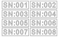 |
Serial number text |
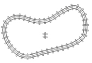 |
Duplication along a curve A kind of duplication tools, you can arrange the objects along a line or a curve. With these functions, you can work out well-regulated and handsome graphs. |
 |
|
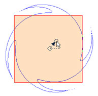 |
Artistic transformation Just like the changeful life. We have to do some complex change when design. Here we offer Perspective Distortion, Envelop Distortion, Push and Pull Distortion and Twist Distortion. |
 |
|
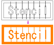 |
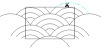
Boolean operation Boolean operation includes join, common, not common and subtract. |
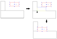 |
Locate and align in dragging While moving, scaling entities, if you hold Atl key, Ucancam can snap feature point as the start, end point of moving, allows you movling precisely, So as to realize fast nesting. |
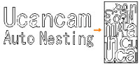 |
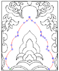
Auto Nesting 1. Parameters setting such as kerf width, cutting margin compensation and Iteration count; 2. Nesting method setting: starting point ((left bottom, right bottom, left up, right up), direction: X direction and Y direction; 3. Precise calculation, such as inside hole nesting, to improve the efficiency of working and utilization rate of material. 4. After nesting, a most economical line and an excess material graphic can be generated automatically. |
 |
|
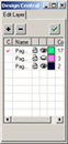 |
Layer management In Ucancam, you can create graphs on different layers that can exist together. You can add or delete layers so as to perform operations on many objects at the same time. |

Toolpaths are calculated quickly and accurately. Ucancam provides a Tools Library where users can choose, edit, add or delete a tool. Various machining solutions are available. Users can apply toolpath simulation to check whether toolpaths are valid and to preview machining results. These simulation functions are also useful to reduce trial cutting times and cut down machining costs and help users to get valid and effective machining results.
 |
|
 |
|
 |
|
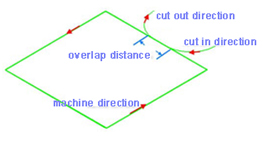 |
Lead in/out When using Lead in/out, the tool first goes into a certain depth outside of material, and then cuts into the side of the material. |
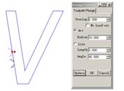 |
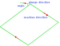
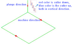
Toolpath plunge You can modify the start point of profile path by click the start point, and keep the left mouse key down, drag the mouse to move the start point. And the same time the plunge will be modified by the parameter of dialog. |
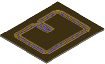 |
Trochoidal toolpath in profile machining |
 |
|
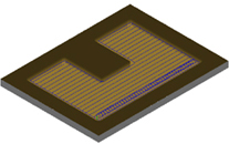 |
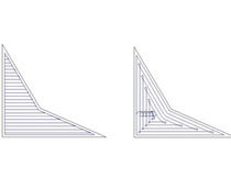
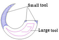
Trochoidal Slot in area clearance Trochoidal toolpaths are mostly used to create slots in double side cutting. You can use trochoidal paths to create pockets, but there will be some wasted movement when the pocket opens up, and the arcing paths are unnecessary to minimize engagement. |
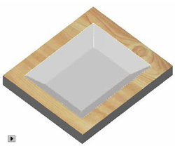 |
3D Corner Engraving |
 |
Midline Machining Midline machining is to machine along the middle axis of the drawing. |
 |
Drilling You can Drilling on points, on curves, on the center of object or in region. |
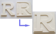 |
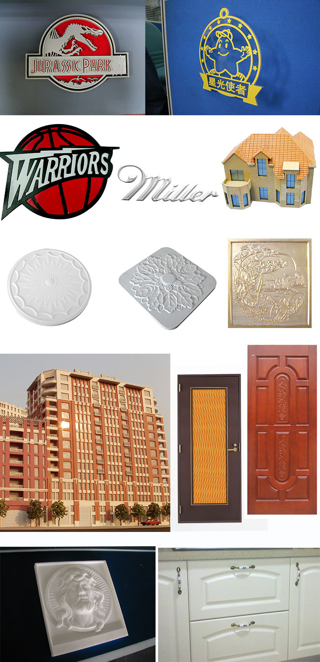
Insert and Inlay This is a special function of engraving. It is an important measure to make sign marks and craftworks. |
 |
Intelligent machining |
 |
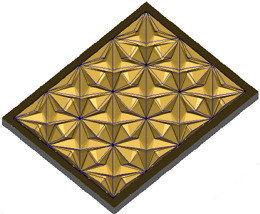
Prism machining |
 |
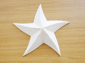
Embossing machining |
 |
Image dot machining Image dot machining is to engrave the object after the image is converted into grayscale image. Dots are made on the material based on the different grayscale value. The higher the grayscale value is, the deeper and bigger the dots are, and vice versa. |
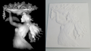 |
Image relief machining Image relief machining is to engrave the object after the image is converted into grayscale image. The machining is based on brightness level. Min brightness depth and max brightness depth are the depth by which the tool goes into the material. Horizontal/vertical machining is the direction of the tool path. |
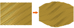 |
Toolpath artistic transform Perspective Distortion and Envelop Distortion can support the toolpath transform. especially can be applyed to the waveboard toolpath. |
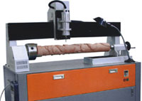 |
Rotary_Axis engraving This is used to drive a machine using rotary axis, do cylinder engraving. |
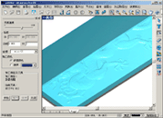 |
Toolpath simulation Machining process can be previewed through toolpath simulation, thus avoiding trial cutting and reducing cost. This function is helpful for choosing a proper machining type. |
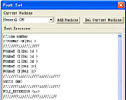 |
Post Processor The Post Processor is a programme which converts the tool path in some standard neutral format into the format requried by a specific machine control system. Such as Biesse, CAMtech, Fanuc, Homag, MasterWood, Microstep, NcStudio, RichAuto, SYNTEC, SCM, etc.. |